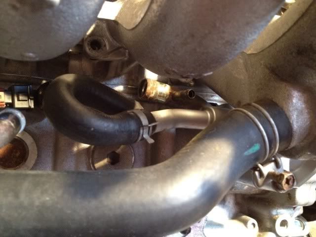


Can someone help me with this, I am trying to work out what to put where. I have this
And I want to do this in the end.
Can someone tell me what to remove? I don't want the throttle body idle control bit or the oil cooler.

Can someone help me with this, I am trying to work out what to put where. I have this
And I want to do this in the end.
Can someone tell me what to remove? I don't want the throttle body idle control bit or the oil cooler.
Speak to Vidal babbon. He's done it and I'm sure I remember seeing a thread on here about it from him also.
1998 Nissan 200sx s14a , 2000 std 5 speed with nismo supercoppermix clutch bn6 Sapphire Blue
Yeah ive found that but there are no pictured of the car on there.
Do I just connect the pipe that goes from the block to the oil cooler onto the thermostat housing instead? So it goes block to thermostat housing and then block the rest up?
Jon to also help you out, try getting the oil filter adaptor plate off a red top SR S13 mate, that way you can do away with the water cooling (warming) and save spacegreat for kit cars
Last edited by Dan@DB-Power; 29-08-2012 at 08:26.
I have a Mazworx oil block sorted out for the space issue. I still think I will need another UJ in the steering shaft to clear stuff!
Looking at the diagram that you have posted you are ditching everything except the radiator cooling system and thermostatic bypass.
Is this correct ? are you not retaining the heater matrix in car ?
This is for his kit car mate so prob no need for it.
1998 Nissan 200sx s14a , 2000 std 5 speed with nismo supercoppermix clutch bn6 Sapphire Blue
Yeah it's for the kitcar. I want to get rid of it all I think.
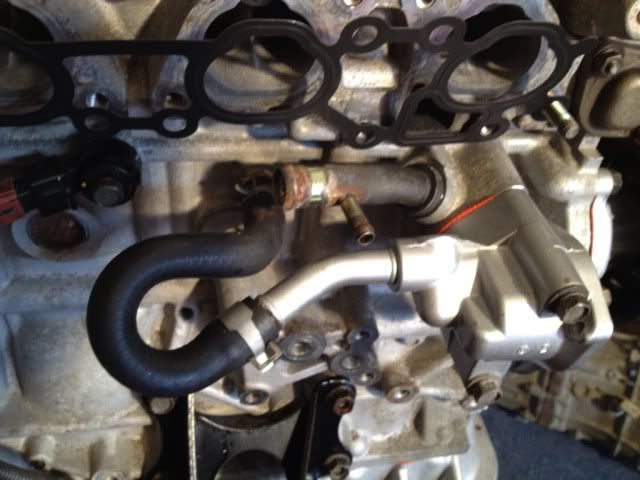
In the picture below I have linked the pipe that originally went to the oil cooler to the back of the thermostat housing but I though about it and I could actually block ends can't I?
Then I guess I need to link the big one in the next pic to the small one that goes into the black behind the thermostat housing?
Where the water flows through the manifold casting is needed so I might as well keep the cold start gubbins.
Yeah thats the badger mate.
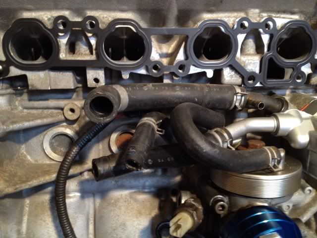
You could block the one on the side of the block that went to the old cooler and also block the other end of the connected pipe that goes to the side of the stat housing if you wanted.
Then just connect the large one in the second pic to the one that has the small nipple on it.
I kept the cold start though as mine is a daily and i thought it may come in handy, more research revealed that it's not an issue binning it
What is the one into the back of the thermostat housing? Just a return. I will remove it then I think. Simpler the better and more space.
Just need a 19mm 180degree bend and a 25-19 reducer then.
I may even be able to use the original pipe to the heater matrix as the reducer
Thanks Nick.
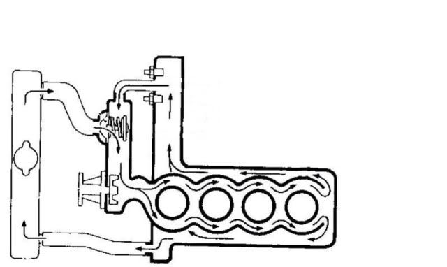
If you look at the original diagram and remember the dotted lines mean there's no connection, then there's two returns to the thermostat housing, one is the circulation path from the head/intake when the thermostat is closed (somewhat important!) and the other is the return from the heater matrix, throttle body and the oil cooler. I don't know which is which on the real car, but I don't think you can mix them up. Probably ends up looking like the attached diagram if you blank everything off (although I'm not sure why you'd remove the cold start for the sake of two tiny pipes).
Similarly, I wouldn't re-route the oil 'cooler' pipe into the thermostat housing, otherwise you might get loads of water flowing that way rather than via the cylinder head. Nissan sell a blanking cap if you want to block it off in a posh manner, as it's not present on the S15 (I looked into this as I was going to FIT an oil 'cooler' to my JDM engine to get the oil up to temp quicker in winter).
I think I will leave the cold start in place is its only 2 pipes. It saves me blocking off the tiny pipe it plums into.
The leg that goes up and has the pipe to the cold start gubbins is the chamber in the manifold I think? The dotted one runs underneath this rather than through it.
I will block the two ends that I have linked then John? So I don't bypass the cylinder head?
Last edited by jon200; 26-08-2012 at 17:31.
I reckon you block the pipe from the block and the thick part of the top pipe (which would have been the heater matrix return pipe).
You'd then loop the thick pipe coming off the plenum back into the downward pointing silver pipe. It would have gone to this originally, just via a Y-shaped piece of pipe which split it between the heater matrix and this bypass route.
Although not physically in the order of the manual diagram, I'd say the silver pipe is the bypass pipe as the thermostat blocks it off when it's fully open (plus the rubber hose going to it is called the 'bypass hose' in FAST)
If the thermostat blocks the silver pipe then won't it stop the flow though from the head?
Nah, when the stat opens to block the silver bypass pipe, it opens the main radiator pipe and all the water out of the head goes through the radiator and back into the stat housing.
In addition, I think a tiny bit always goes from the head through the throttle body, no matter what the stat's doing.
The cooling circuit diagram seems to back this up (the thick black arrows and the hollow white arrows show the 2 possible paths, switched by the 'stat ).
Here's a rough piccy
Last edited by John Bennett; 26-08-2012 at 17:27.
Thats an excellent picture
It isn't that obvious, but I reckon that:Originally Posted by jon200

The other pipe to the thermostat housing is always open (the thermostat position doesn't affect it) so when the engine's warmed up, you'd be providing an unwanted alternative circulation path from the head back to the pump/block (which would bypass the radiator and not get cooled).
The idea of the stat is to provide a bypass when cold and remove the bypass when warm.
I made a slight tweak to the diagram to show the thermostat moving.
Last edited by John Bennett; 26-08-2012 at 17:30.
The thing I keep looking at is the size of the pipe from the inlet bit and how much it gets reduced down to. I guess it would normally be split through the matrix and oil cooler anyway so the flow will probably be more/faster?
Does the water flow through the matrix all of the time? Even when you ask for cold.
Thanks for helping me out John, you certainly know your stuff.
 Posting Permissions

 Reply With Quote