-
Guest


-
Guest
Dakota digital/speedometer wiring help
Hey mate,
Sorry to hijack
Not sure if I have the same question as you, or that you may be able to answer mine.
Which wire is the speed sensor going into the back of the speedo cluster?
I thought it was 22, but I have spliced this and used a speed converter from kbtv and it does not convert from kph to mph (22 is what he identifies in his fitting guide - but he states it is yellow?)
Any ideas?
Cheers
Chris
EDIT:
Not sure what I have even cut, I think hes describing 22?
http://kbtv.info/fitting/NISSAN-SILVIA-200SX.jpg

Last edited by CEmm; 02-03-2016 at 18:36.
-
Guest
Hi,
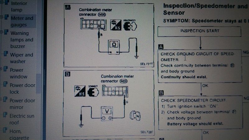
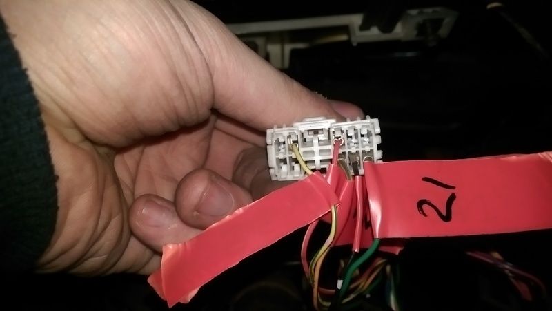
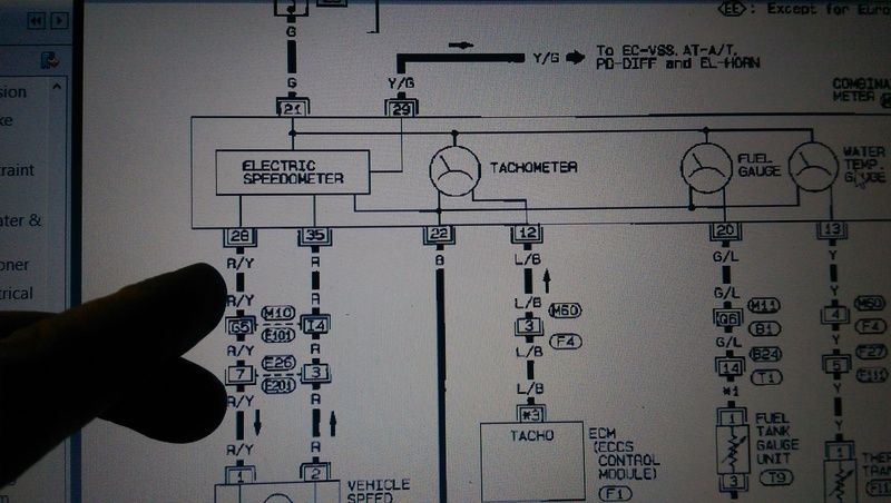
I traced the board on the cluster to find the speedo wires etc then looked at the FSM. if you imagine the plug im holding upside down, then the wires are:
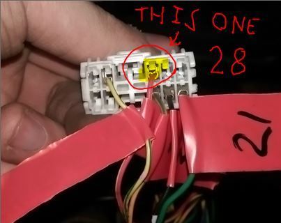
22 by the FSM is a ground (black wire) 21 is ign power (green) and 28/35 are signal wires from the sensor (yellow/green 29 and red/yellow 28).
-
Guest
Was thinking that when i was typing, replace where i say 22 with 29 and it should make sense??
-
Guest
Sorry what does FSM stand for?
So ive tried 29, ill try 28 to see if that is the speed sensor?
Ill delete these comments in a bit mate to give you your thread back!
-
Guest
Looks right to me, just rotated 180.
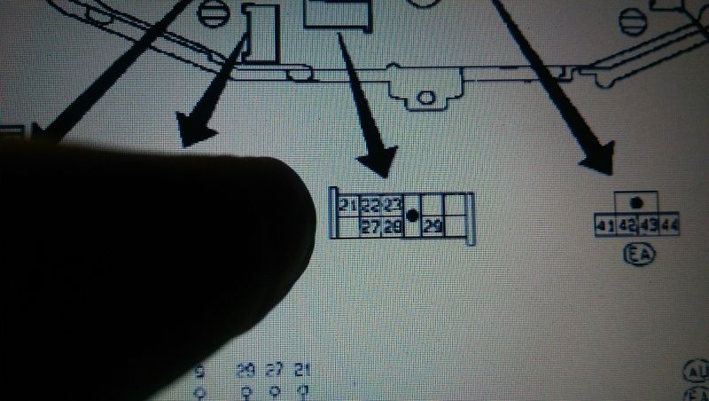
You do seem to be missing a wire for pin "27" - you don't show the full page from the manual, I suspect it's for something you don't have like auto "O/D" warning light.
Pin 35 will be on another 10 pin plug (under your big finger?). Plug 1 pins 1-10, plug 2 pins 11 to 20, plug 3 pins 31 to 40 and plug 4 pins 41 to 44.
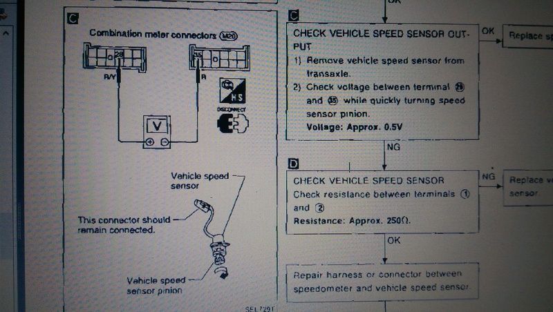
The speed sensor is a pulse generator that produces 0.5V AC so it shouldn't matter which you connect to.
Have you tried windows start, all programs, accessories, snipping tool?
Or
Acrobat reader, right click on toolbar, edit tools, take snapshot?
I've no idea which connector this is but it's not the one above. Pins 31-40?
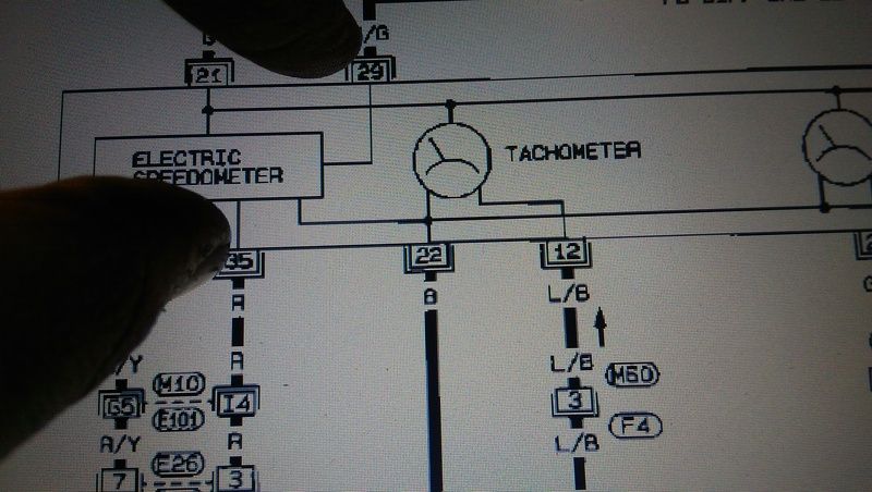
If that red wire with a bit of brown tape round it at bottom right is pin 35 then it will do.
No shouldn't be pin 22 at all. That's black and is the earth.
Pin 28, Red wire with Yellow trace.
Pin 35 RED wire.
FSM = Factory Service Manual.
-
Guest
Dakota digital/speedometer wiring help
Sorted!!
Red with the yellow worked!!
So the black is earth (22) do you know which is power? So i can run this converter behind the clocks and dont have to run this wire from the fuse box
Cheers
Last edited by CEmm; 02-03-2016 at 22:34.
 Posting Permissions
- You may not post new threads
- You may not post replies
- You may not post attachments
- You may not edit your posts
-
Forum Rules


 Reply With Quote