-
Guest

speedo wiring how exactly does it work ?
Hi all,
how exactly does the dash speedo work? Does it only need the 2 wires from the speed sensor from the gearbox? Cause I've now tried that on 2 different cars with 2 different clusters each, and no go?
-
Guest
Speedo has 6 connections. You need at least 4 of them.
24 Power. Green wire to 10A fuse 1 up from bottom in front row of drivers side kick panel.
28 Earth. Black wire to body ground on brackets at each end of dash support bar.
6 and 12 Speedo sensor. Yellow/black and yellow/blue these are on 2 different dash connectors (not the one with power and earth)
Outputs - don't think these are needed for speedo function.
7 Speed to ECU and auto control. Yellow/green.
13 diff oil cooler 10 Km/h switch. Yellow/Red. (just to confuse there are 2 yellow/red wires on this connector, the other is pin 19 tacho to ECU and auto)
-
Guest
Ok, I have it wired up exactly as you say. I do have a Ka24e gearbox though, would that be a problem? If not, is there a simple way to test either the speedo or the speed sensor?
-
Guest
Speed Sensor Signal Check:
1: Remove speed sensor from transmission
2: Turn speedometer pinion quickly and measure voltage across a and b (appro 0.5V Alternating current)
So testing the sensor is easy, now I still have 2 questions, how to check the gauge and will a ka24e Box/sensor work on a ca18 dash 
-
Guest
KA gearbox is the same as a CA/SR/small RB.
what does the speed sensor you have look like? the CA ones have a red gear wheel on the end.
is yours just not registering a speed at all when connected?
-
Guest
Nope, does nothing at all. Haven't looked at the speed sensor itself yet though, it's still as Nissan intended a few decades back
I've rebuilt the wiring of the entire car from the ground up, and this is actually the only thing not working. I'll try to find a cluster that is definately working, to rule that part out.
-
Guest
as has been said,
jack the back wheels up nice and safe
drive the car with the wheels raised unplug the speed sensor
pop your multimeter on the plug and you should get a varying reading.
I cant remember if the signal goes to the ecu then the clocks or the clocks then the ecu.
-
Guest
that last part doesnt matter, I removed most of the wiring including the feedback speed to the ecu 
-
Guest

I'd just pull the sensor out and put it in a drill, turns it fast enough to get a voltage
-
Guest
Well this is strange... I get a nice 0,5 - 3v A/C signal from the sensor, and the distance meter actually responds normally. The speedometer sort of works, but it reads REALLY low, It will read 20 km/h when I'm doing 80... I'll see how far I can get by adjusting the pot.
-
Guest
Well, no need to adjust anything. I was cruising down the freeway, and suddenly the speedometer popped into action Went out a few times, but at least the wiring is ok, just the speedometer itself that needs some soldering
-
Guest
So I tried to solder the speedo, but there's not really an improvement in the working of the unit. It doesn't NOT read, it just reads VERY low, for instance 20 when I'm going 120. Is there any reason why it would do this? Is there a specific component I could resolder to fix this issue?
-
Guest
Next to the above post, I could use some help on something else
I'm retrofitting the speedo in a 1978 toyota carina, and either i have a broken unit AGAIN or im doing something wrong. I got 12v earth and the gearbox signal going to the speedo unit, but it doesnt work. Does it NEED the distance meter part attached to measure speed? There's also a fifth connection on the speedo board itself, it states 10k ohm, any idea what that does?
-
Guest
have you stripped the 'dash clocks' down into separate parts? (to go in your carina)
what clocks do you have? Uk spec CA180det ones or some weird foreign KA20 ones?
looking at page EL57 of the UK manual shows that pins 6 speed sensor input/12 speed sensor output/24 switched live/28 earth should be enough to get the speedo to work.
its been years since ive stripped some clocks down so cant remember what goes on inside them.
-
Guest
yep, stripped them down. Normal uk/euro spec ones. Yeah, the manual doesn't show that extra connection. I had to pull the needle off, and with that action the pin came out of the speedo instead of the needle coming off the pin, might have destroyed something that way. I'll try to see if it works with a different cluster an unmodified one.
-
Guest
that's exactly what happened to me when I tried to strip my last set of clocks down I buggered the pin that the needle sits on.
the gear on the end of the speedo drive in the gearbox can strip/wear out, so I would check that. and put it onto something that spins fast and measure the output like you did before. they can also corrode inside and start to push the black plastic cap off the back. bad ones will crack the housing.
-
Guest
I've measured the output from the gearboxsensor, it's fine, hits the right A/C voltage. I've tested 3 different clusters now, and none of them work, so I guess it's not just those 4 connections on the back of the speedo. Can somebody please measure what the 5th connection should be? It says 5k on it I don't have a working s13 to measure it in 
-
Guest
i don't understand what you mean by 5th connection. you have 3 plugs on the rear of the clocks, a black one, the middle one and the right side one.
ive grafted s13 clocks into other cars before when doing CA conversions and totally rewired my own car from scratch and retained the clocks so im 100% confident you can get them to work. they are real simple.it tells you what each wire is for on the rear of them..
at a guess if you have all the ones listed above connected then you must have missed off a power or an earth wire.
-
Guest
I'm not talking about the entire cluster, I'm only talking about the speedometer unit itself. The speedo itself has 4 connections/screws in the center, and on in the left top side.
In this picture its the one (open) connection exactly to the right of the brown lightbulb connections, the one running to one of the plugs:
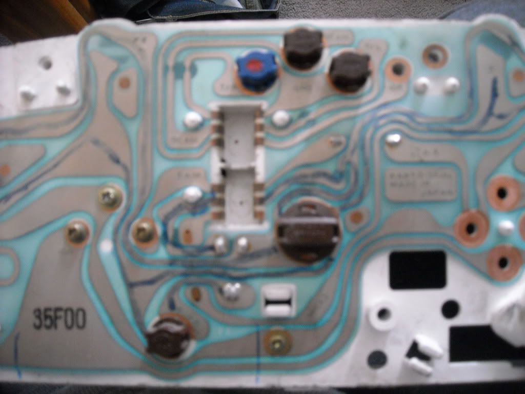
you can also see the 4 obvious connections, 12v, earth, gearbox sensor 1 and gearbox sensor 2. It's that 5th one I'm curious about
Also, concerning the gearbox signal, polarity doesn't matter right? I.e. doesn't matter if the gearbox sensor wires are switched?
-
Guest
ive never done it your way, ive always grafted the whole cluster into the new vehicle.
the speed sensor can be connected up any way round to the cluster,
maybe your mystery 5th connection is the diff oil cooler output, that tells it to switch on as you are going fast.
 Posting Permissions
- You may not post new threads
- You may not post replies
- You may not post attachments
- You may not edit your posts
-
Forum Rules


 Reply With Quote